A Prosthetic with Pockets
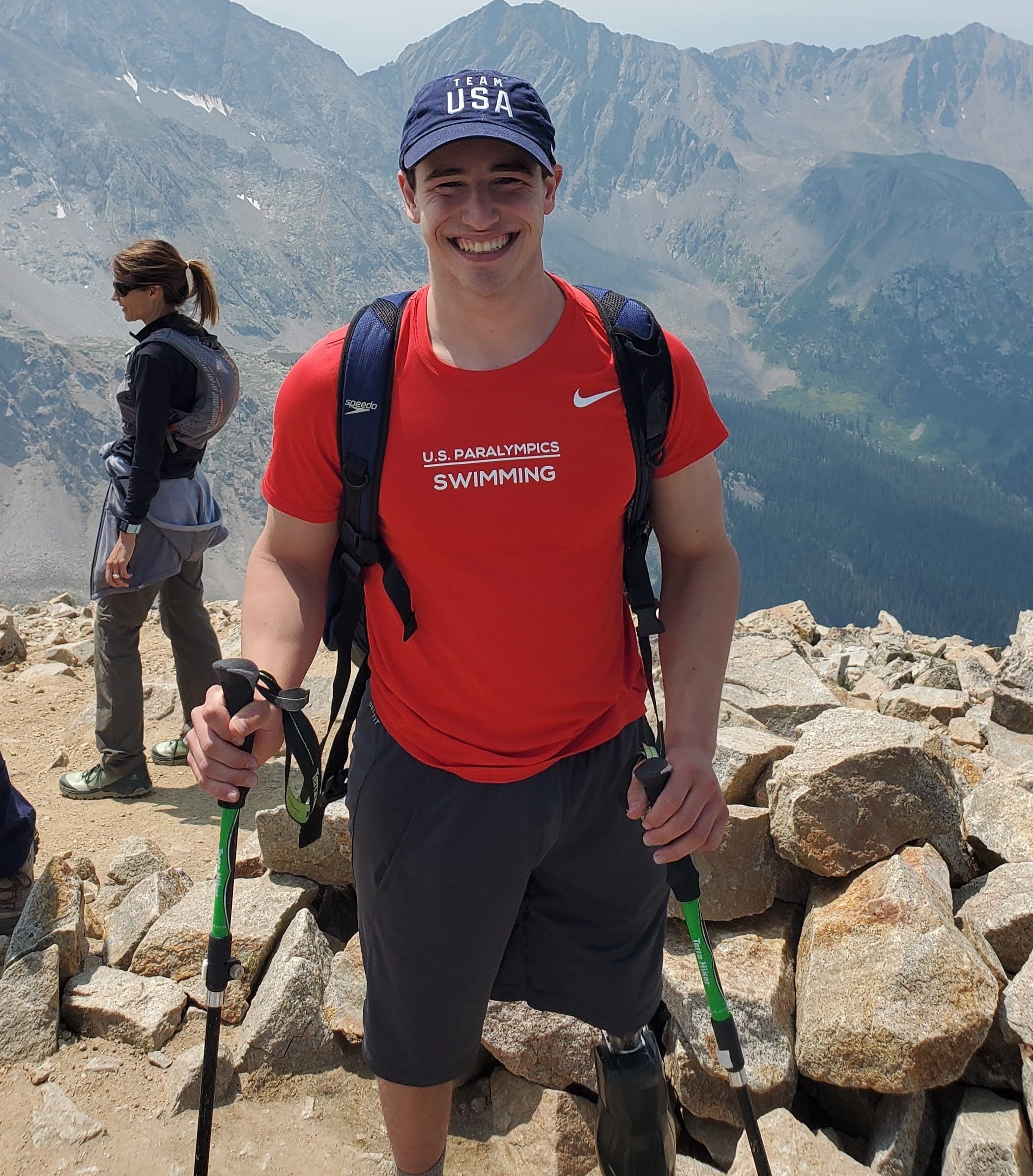
Leg Locker is a project originally conceptualized by our classmate and paralympic swimmer, David Gelfald and our classmate Jeffrey Blitt . David wears a lower limb prosthetic on his left leg and noticed that there is a lot of unused space within the leg. Being able to store food, liquid, or small objects within that space would add extra utlity to an already useful device for David. He suggested turning this concept into our final project for senior design.
Our Motivation
Why mess with a good thing? For the million who rely on them for accessibility, mobility, and social inclusion, prosthetics are an invaluable resource. Advancements in technology in recent years have allowed many prosthetic users to do almost everything they would before the loss of a limb. However, these developments have also typically focused on that concept of restoring the "before" instead of the possibilities for "going beyond" in prosthetics. This medical approach to prosthetic development has helped the assisitive technology industry produce reliable, functional, and integratable prosthetics. However, prosthetic abadonment and rejection is still high among amputees because of the limitations in prosthetics in carrying out advanced tasks.
Our Team
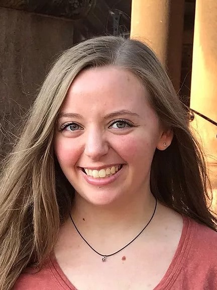
Allison Moore
Design & Component Interfaces
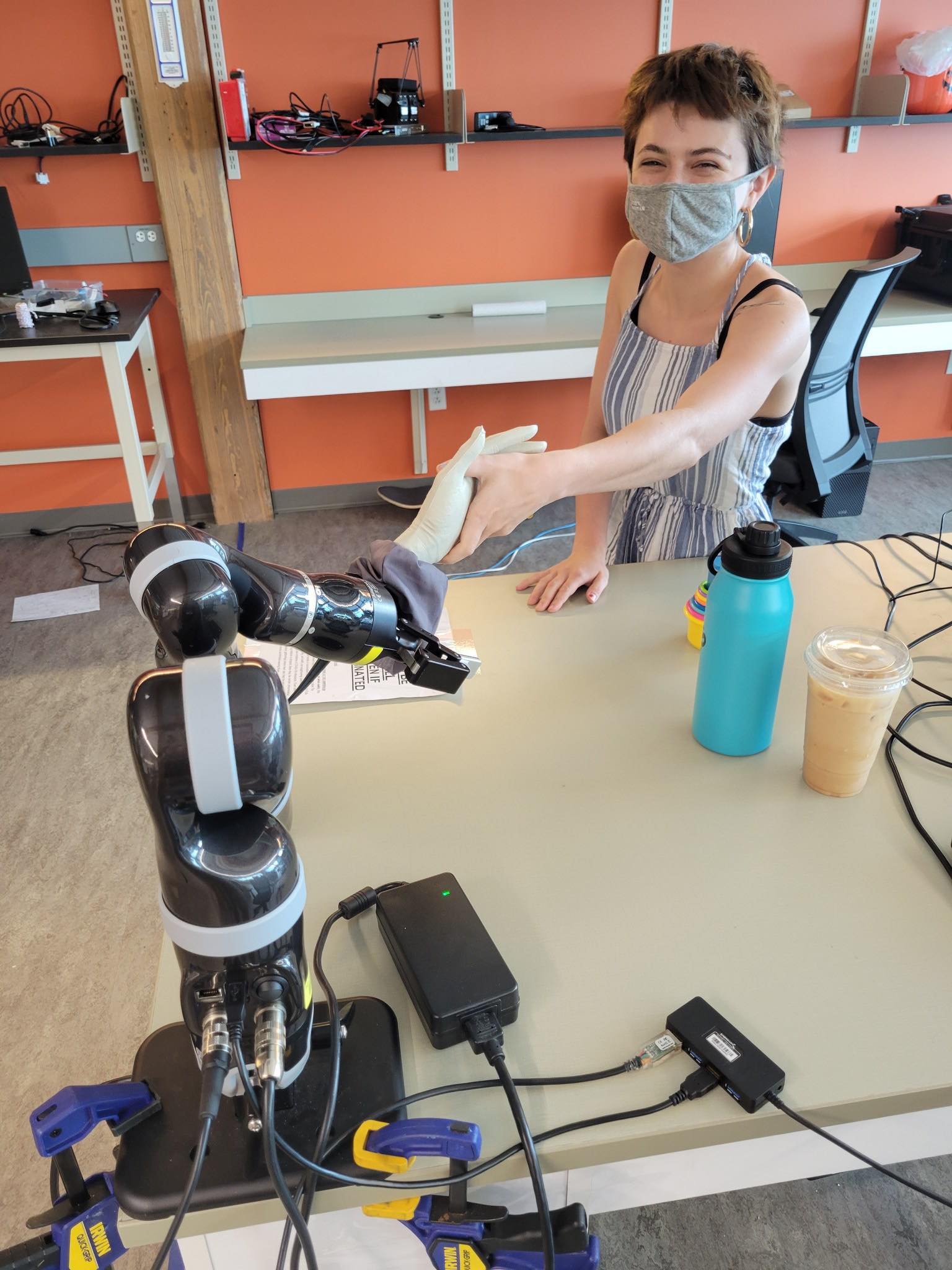
Megan Jenney
Code & Electronics
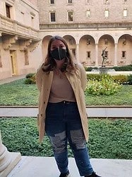
Niki Alden
Materials & Polymer Lead
David Gelfand
Design, Fabrication, & Leg
Planning and Development
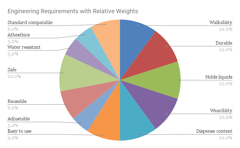
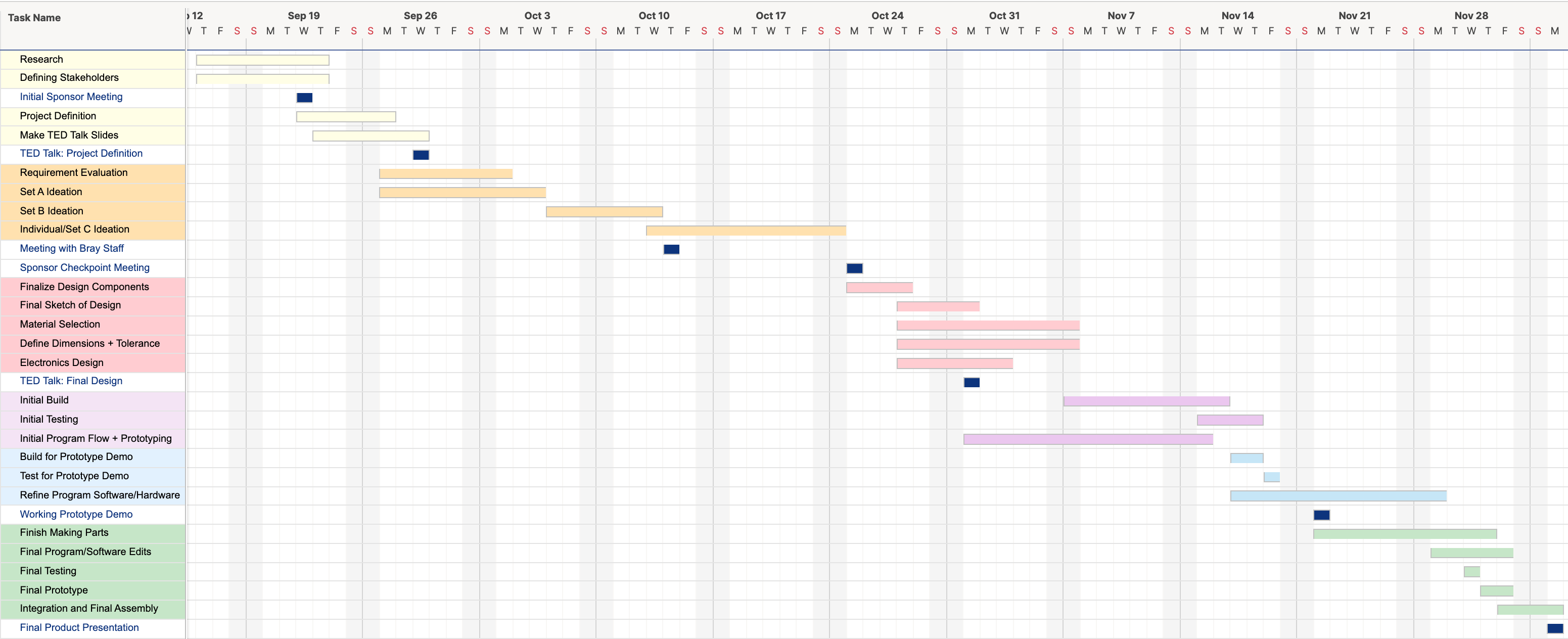
We began our design process by reviewing the current state-of-the-art in prosthetics. In addition to reviewing current literature and products on the market, we relied on David’s expertise as a lifelong prosthetic user and as a member of many prosthetic-using communities. We also solicited feedback from prosthetists at Spaulding Rehab for a more professional opinion. Surprisingly, there is almost nothing like “Leg Locker” currently on the market. In our research, we found that the majority of medical prosthetics are focused on being as close to biological legs as possible. While some “alternative” prosthetics have been developed by groups such as the alternative limb project , they are usually highly individualized and geared toward artistic commentary over enhanced functionality. Given this state-of-the-art, we were excited to move forward with our development of the Leg Locker and our exploration of the concept of enhanced functionality for prosthetics. Having investigated the current state of prosthetics, we developed engineering requirements to direct our future work and planned out our timeline of work using a Gantt Chart. We also further explored measurement metrics for our design requirements using a House of Quality.
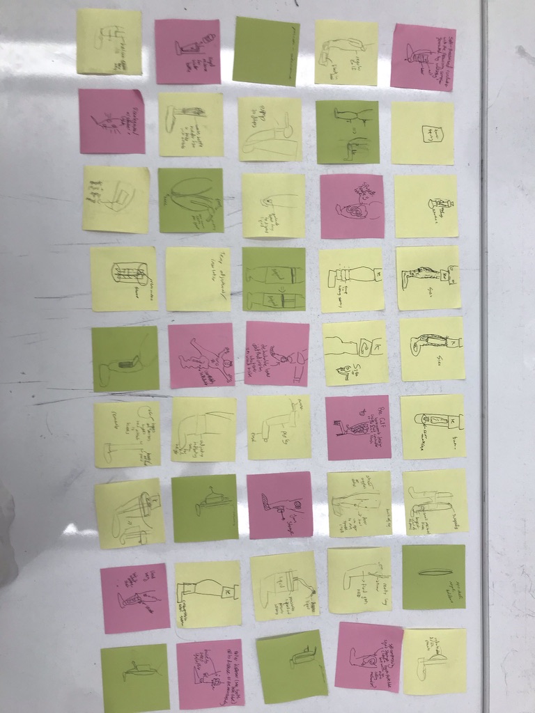
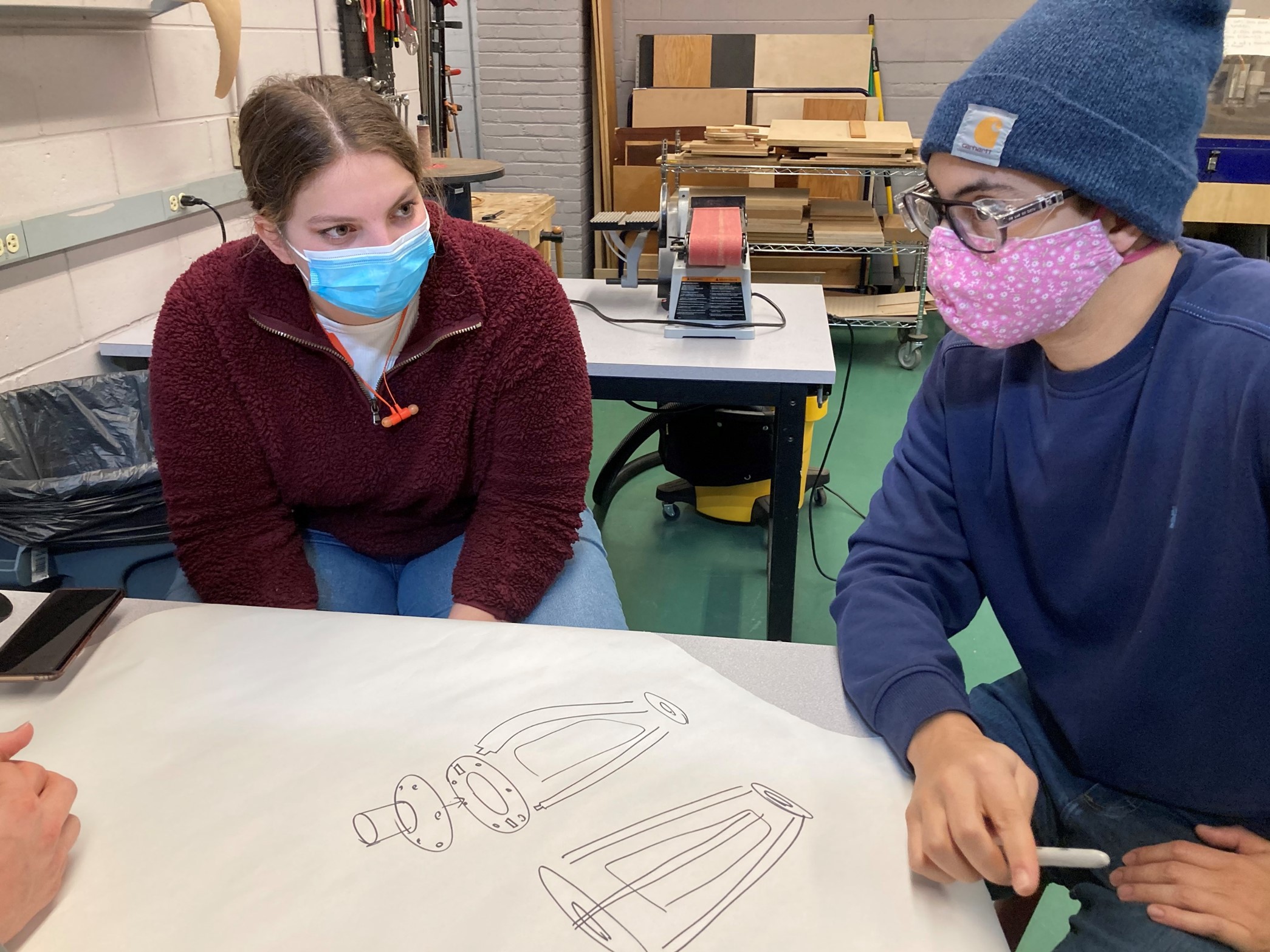
Ideation and Brainstorming
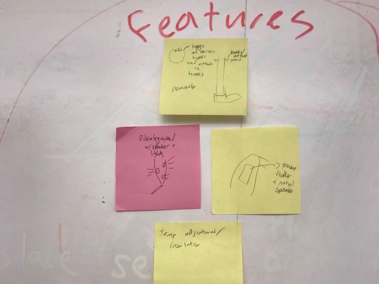
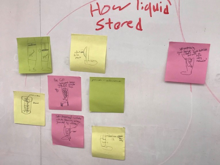
Set A: Brainstorming
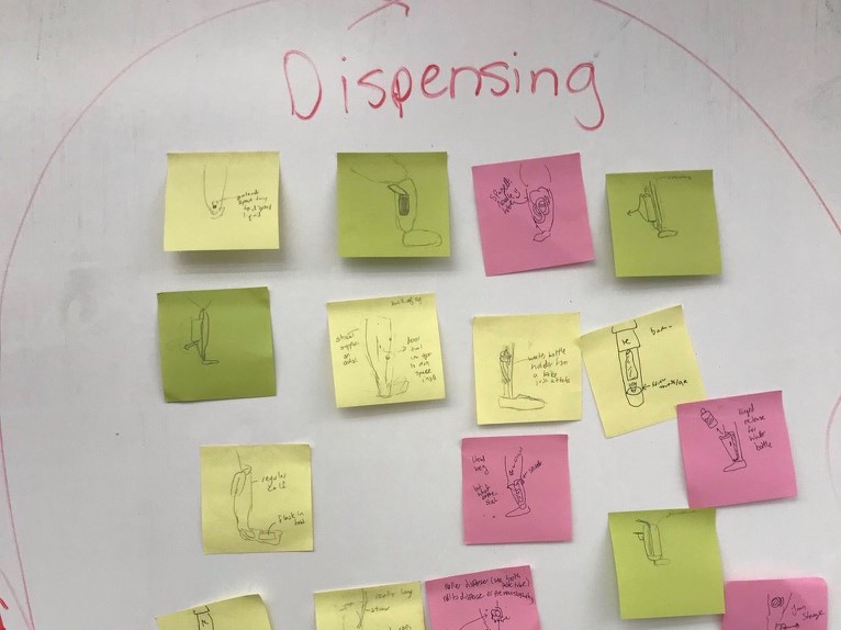
While useful, a leg with pockets is a funny and out-of-the-box idea! With this is mind, we were excited to see what designs we would be able to develop if we started brainstorming with some creative "anything goes" thinking. To create space for a range of designs, we split our brainstorming session into three sets: Set A, Set B, and Set C. We used 15-minute design sprints and affinity mapping to generate a spectrum of smart, silly, and "smart and silly" ideas for our Set A: peristaltic pumps, disco legs, toothpaste tubes to squirt out water, etc. We then split these ideas into relevant categories using affinity mapping.
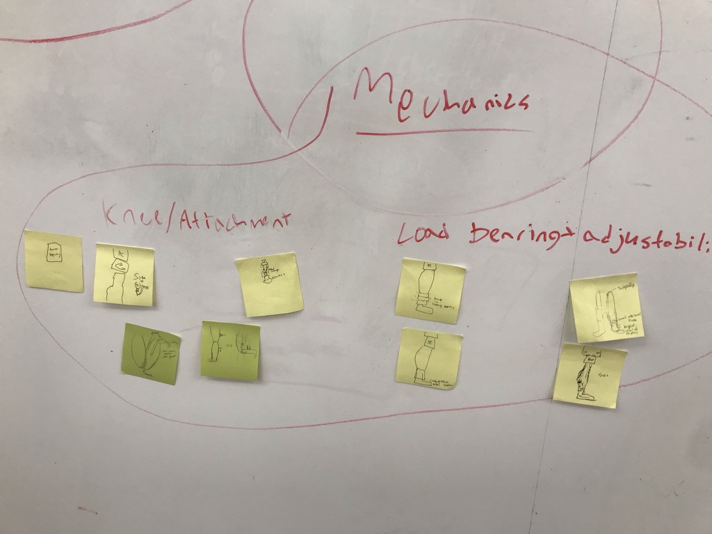
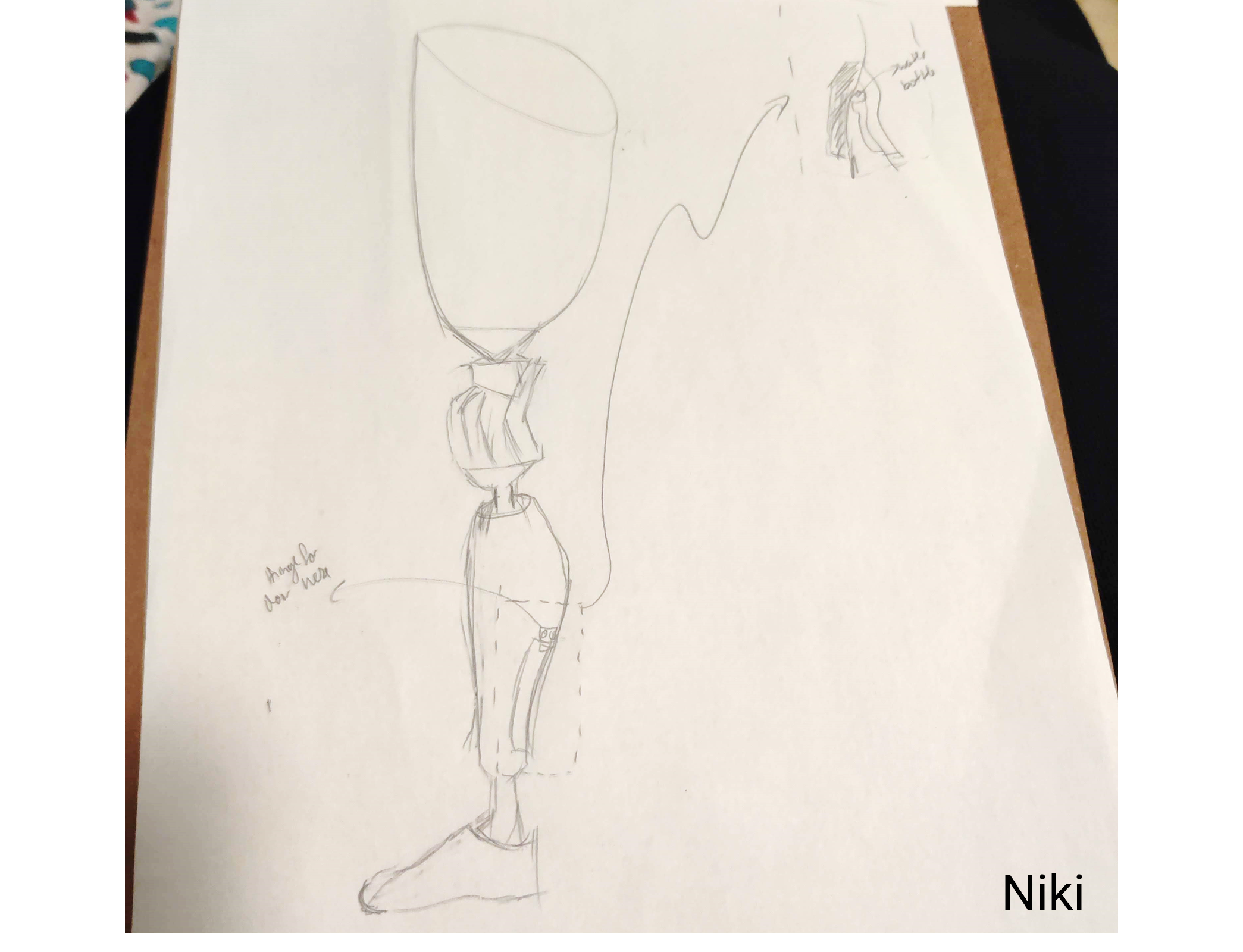
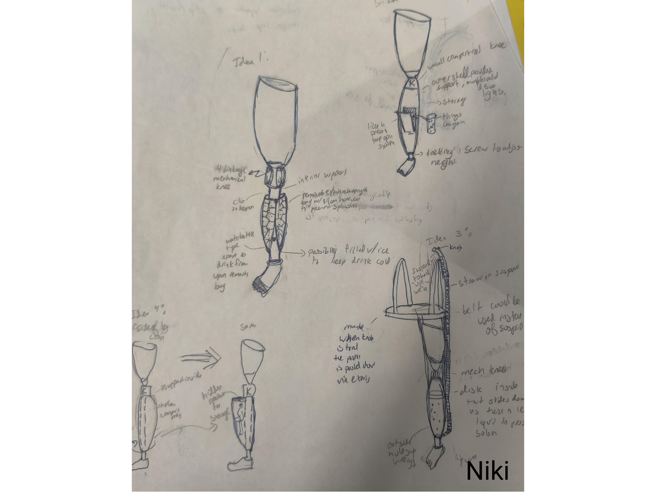
Set B: Refinement
For our "Set B" of design, each group member generated 2-3 designs with more thought and enegy put into them. We reflected on these designs as a group and solicited feedback from our peers, instructors, and machine shop fabcriation experts in Bray Labs.
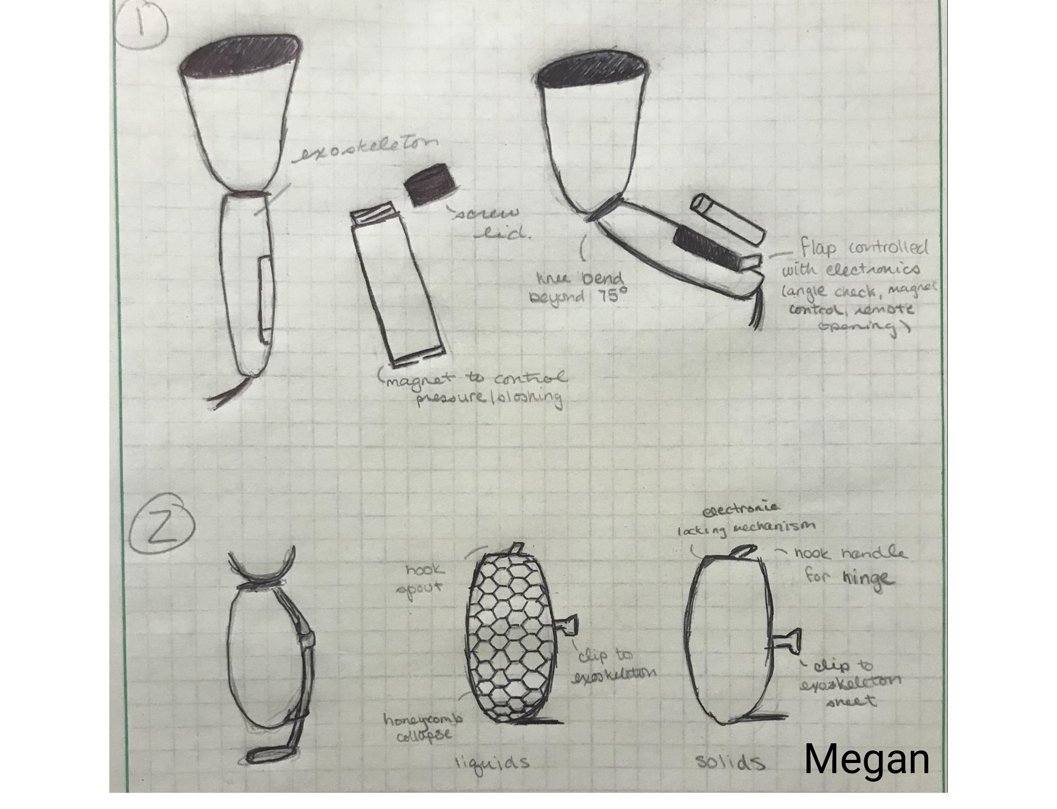
Set C: Proposals
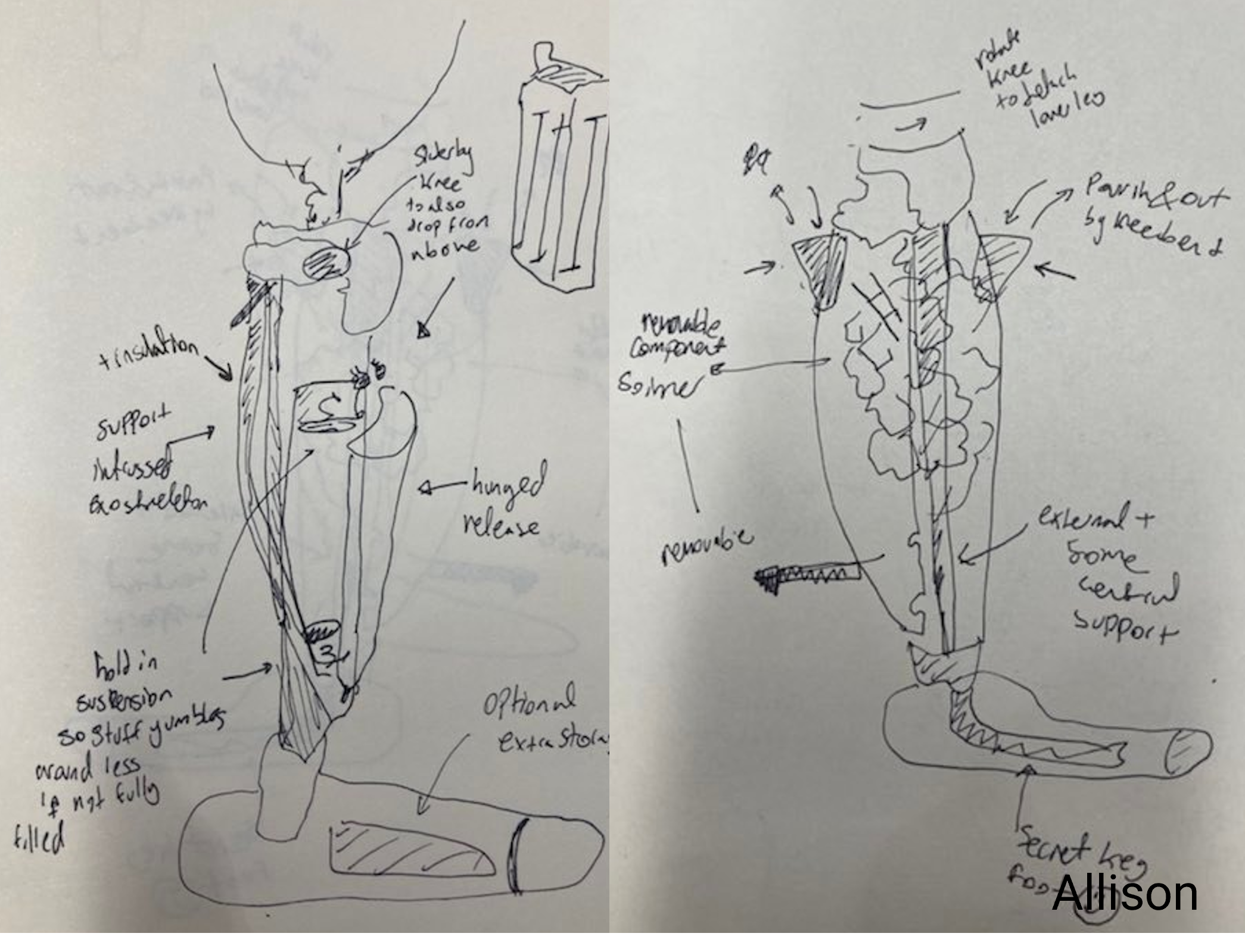
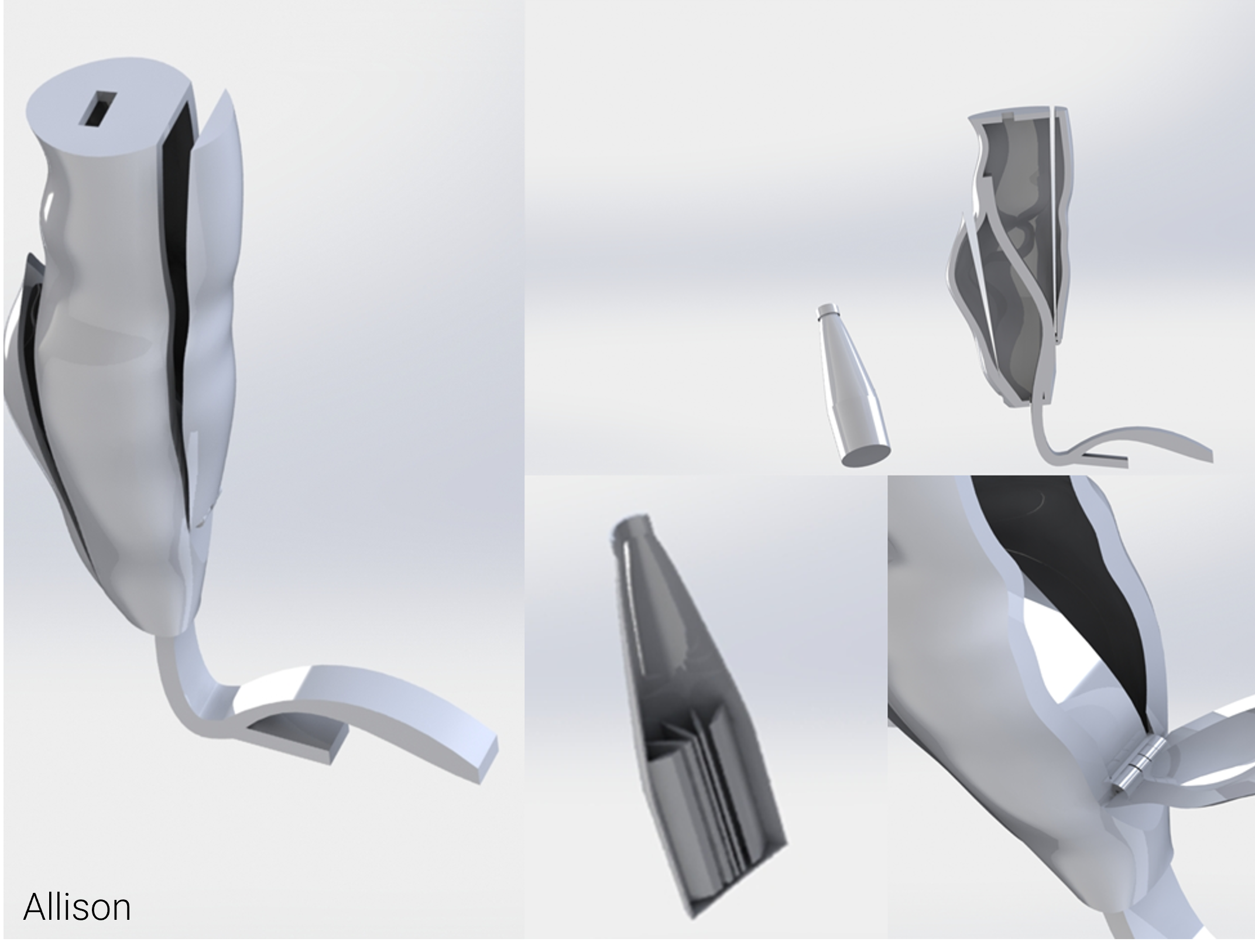
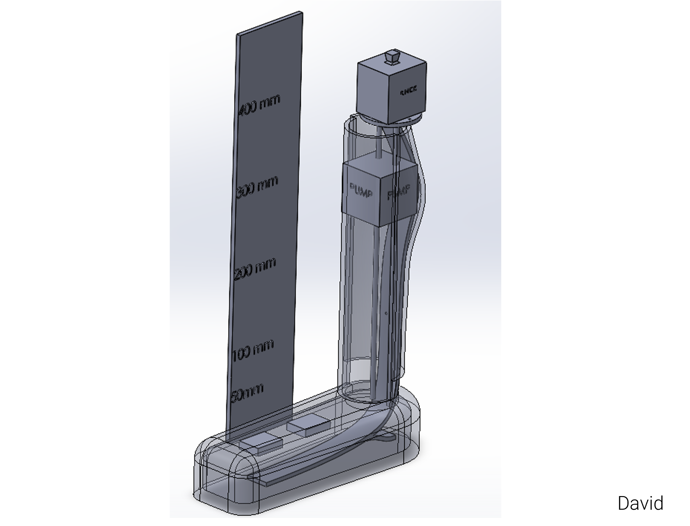
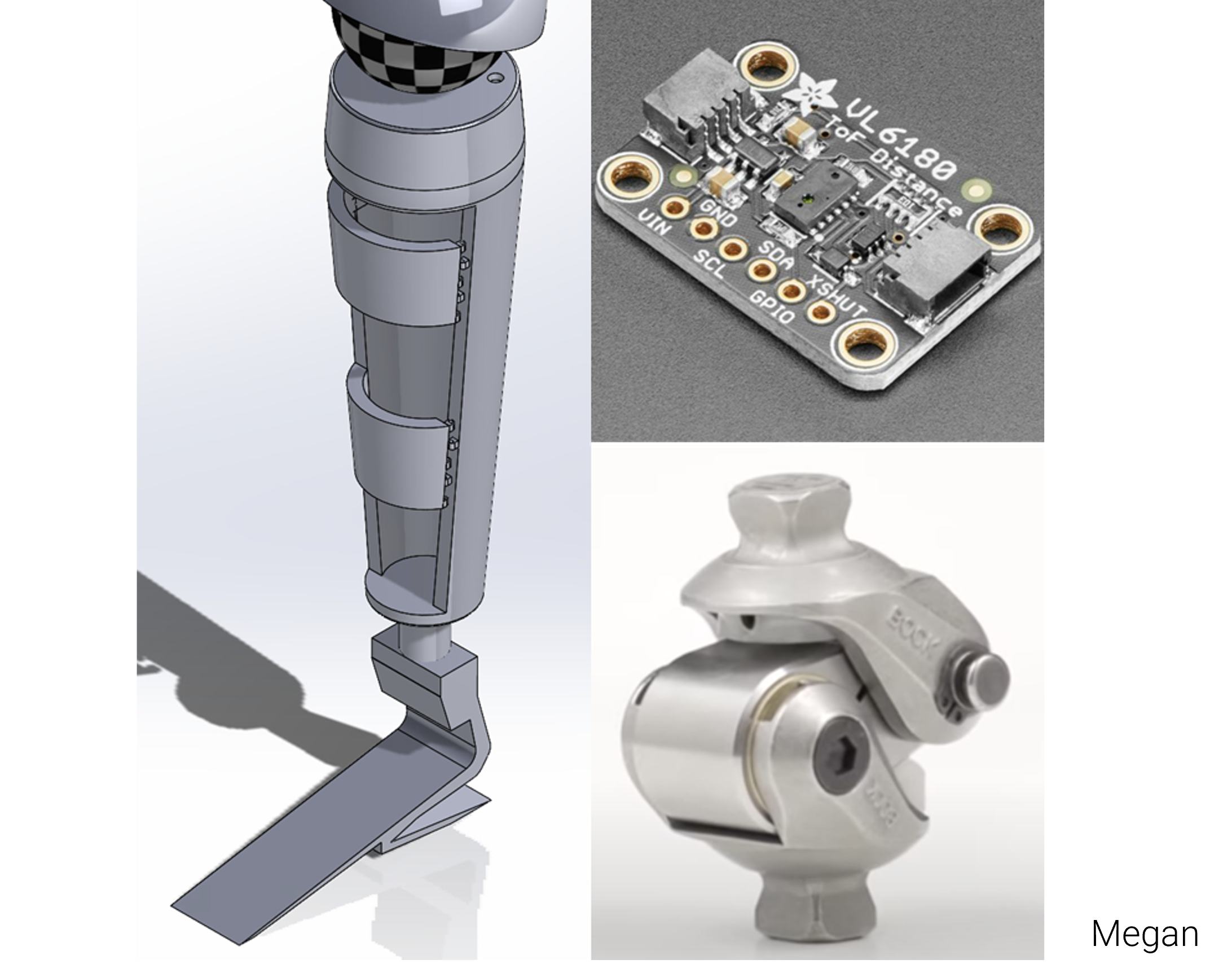
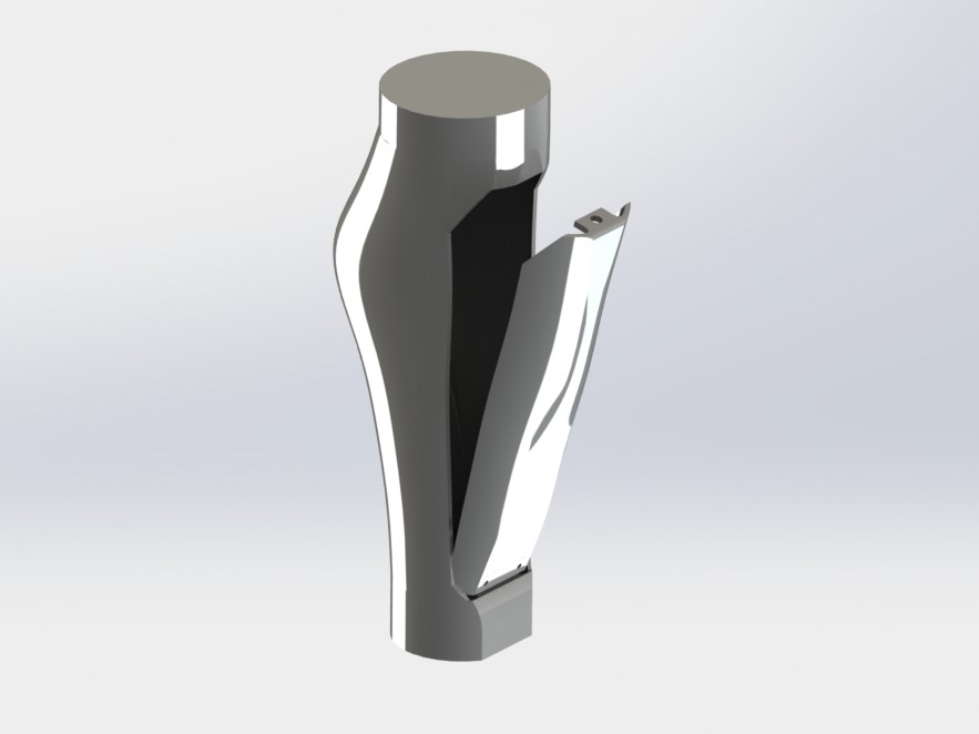
For "Set C" of our design, we each created a CAD model of one proposed solution. I proposed a hinged storage component within the leg with a suppotive exoskeleton outside the leg and two access compartments. Niki proposed a soft bag and straw mechanism for a leg focused on storing water. For a similar water storage leg, David proposed a peristaltic pump mechanism with a soft water bottle held in suspension. Megan focused on electronic componenets and proposed an unlocking mechanism with a door based on the bend of David's Knee.
Final Design
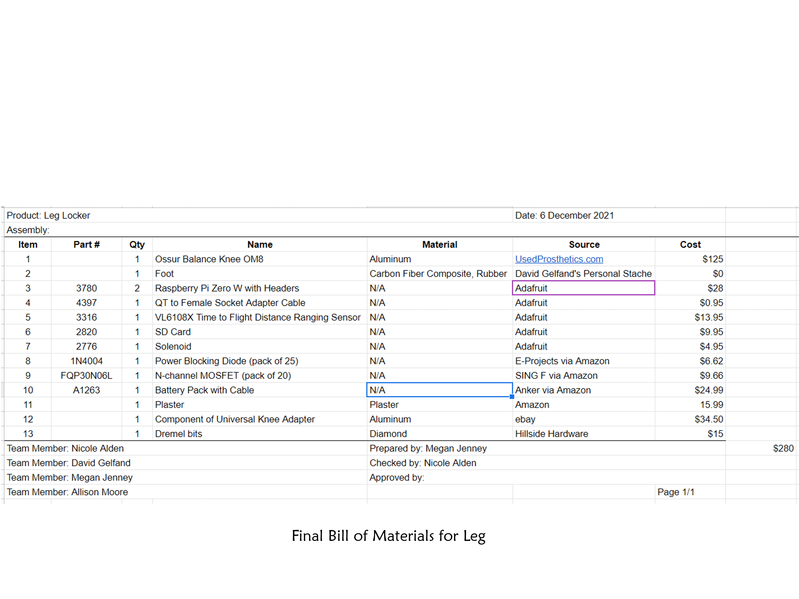
For our final design, we consulted with our sponser, Gary Leisk, to combine features suggested by different team members into a comprehensive product. Our concept used a single hinge secured by a solenoid locking mechanism to keep the door closed in place. We based our main model on my idea of a hinged design to allow for the storage of both solid and liquids with easy access, through a solenoid activiated a high knee flexion threshold. Water can be stored in the solid/liquid compartment in a soft water bottle inspired by David and Niki's designs. We make our device universally adaptable with a pyramid connector welded between the shin and the Össur Balance OM8 mechanical knee.
Fabrication and Construction
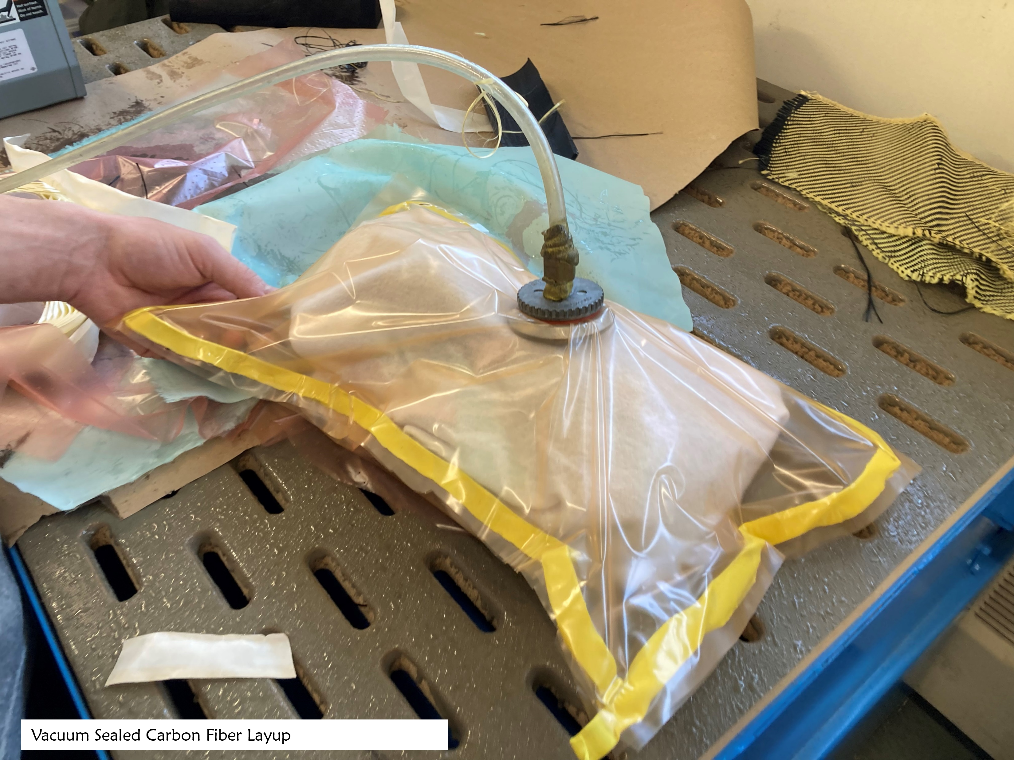
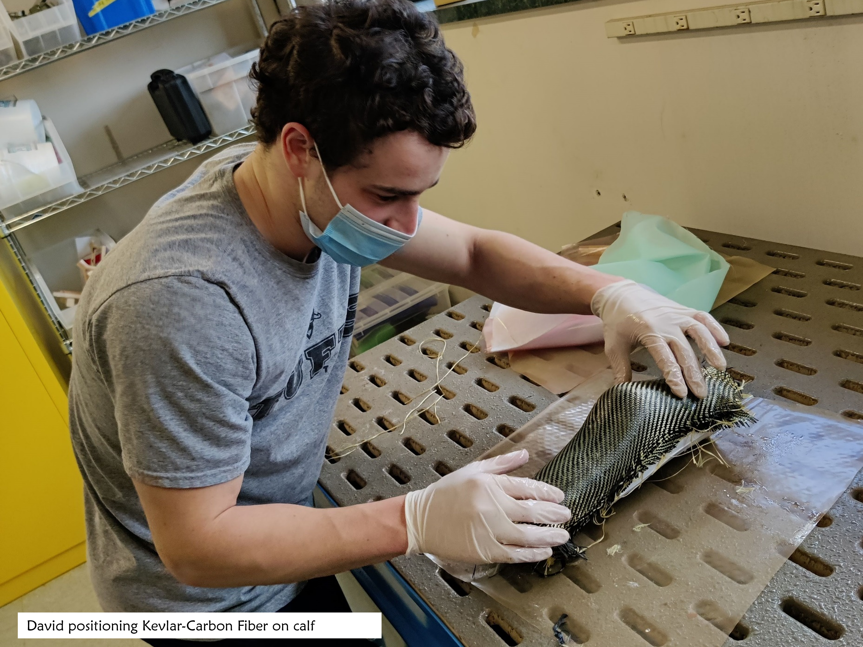
Carbon Fiber Layup
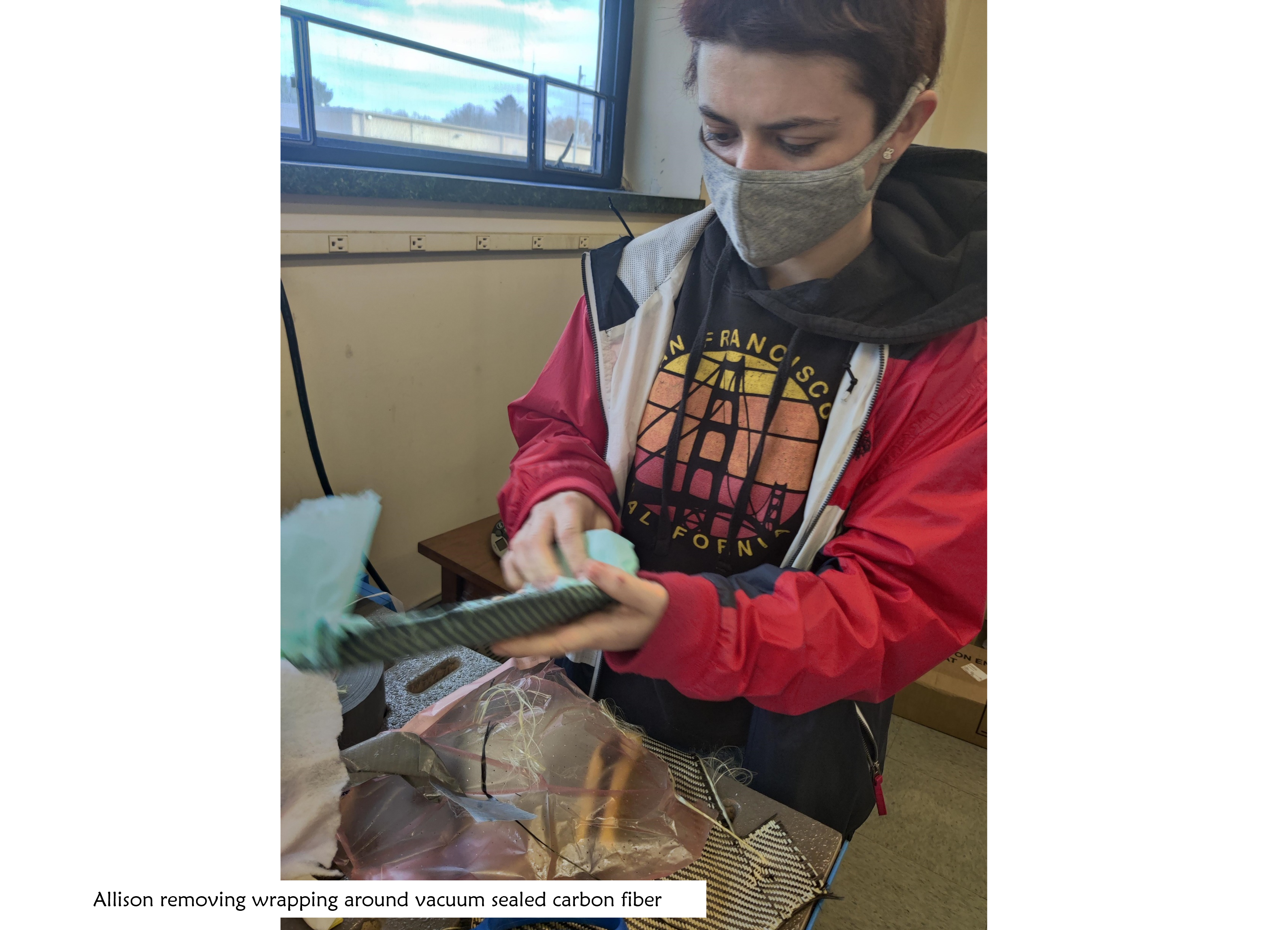
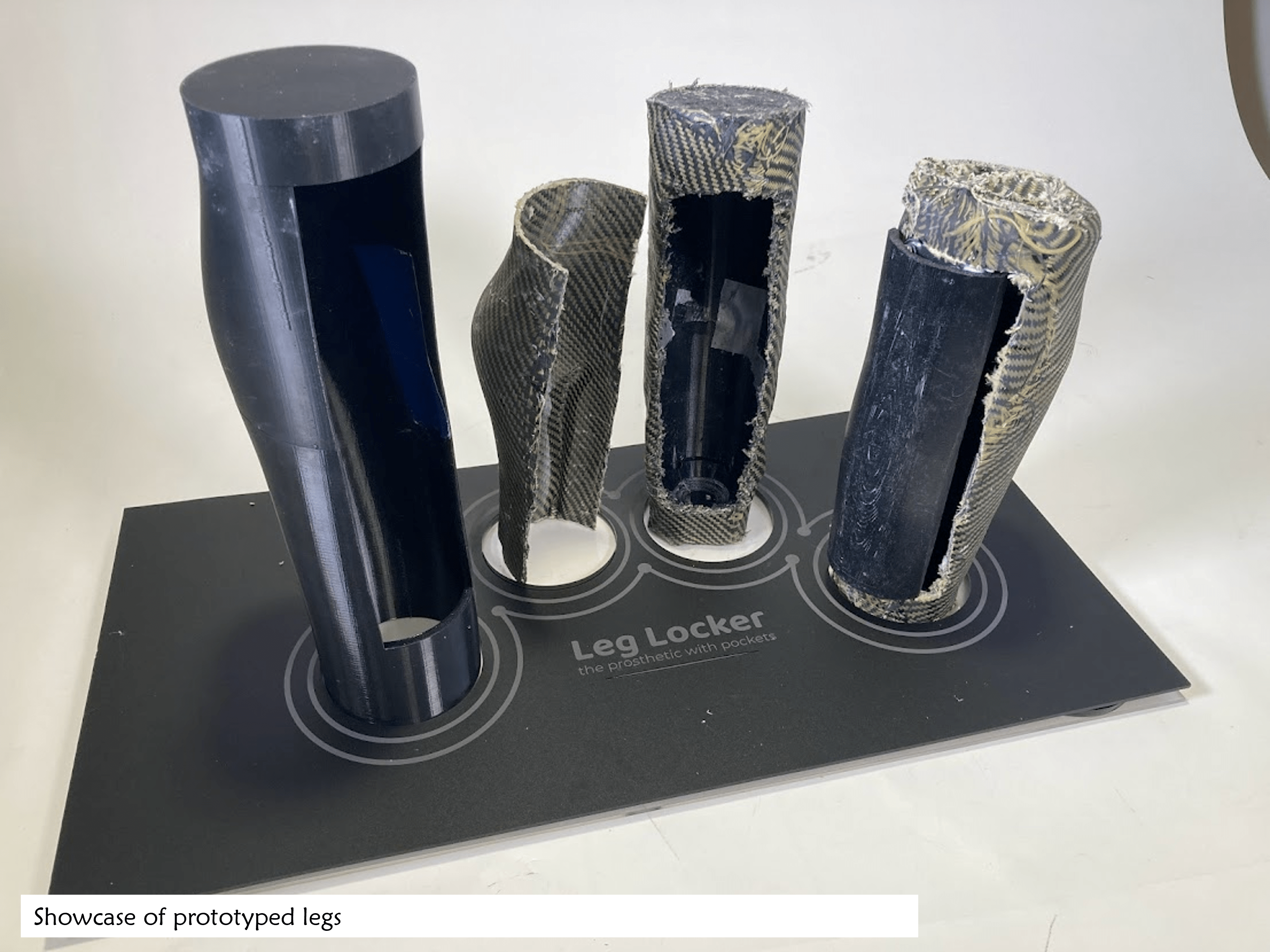
We decided to use a Carbon Fiber exoskeleton to create the main body of our leg. This design choice was based on the common use of carbon fiber within the prosthetics field as well as on our need for a strong leg exterior since "Leg Locker" does not have internal support tubing common amoung many lower-limb prosthetics. To creat our exeskelton, our team used a positive lay-up over a 3D print of the leg. Although we initially experimented with a range of negative layup techniques, we were not able to produce as high quality of a product with a plaster based mold as we were able to with vaccum sealing the positive model. Our final layups were composed of 6 layers pf Kevler Carbon Fiber due to its increased mallubility relative to pure Carbon Fiber. We coated each sheet in an epoxy solution and then vaccum sealed the full leg to set the mold.
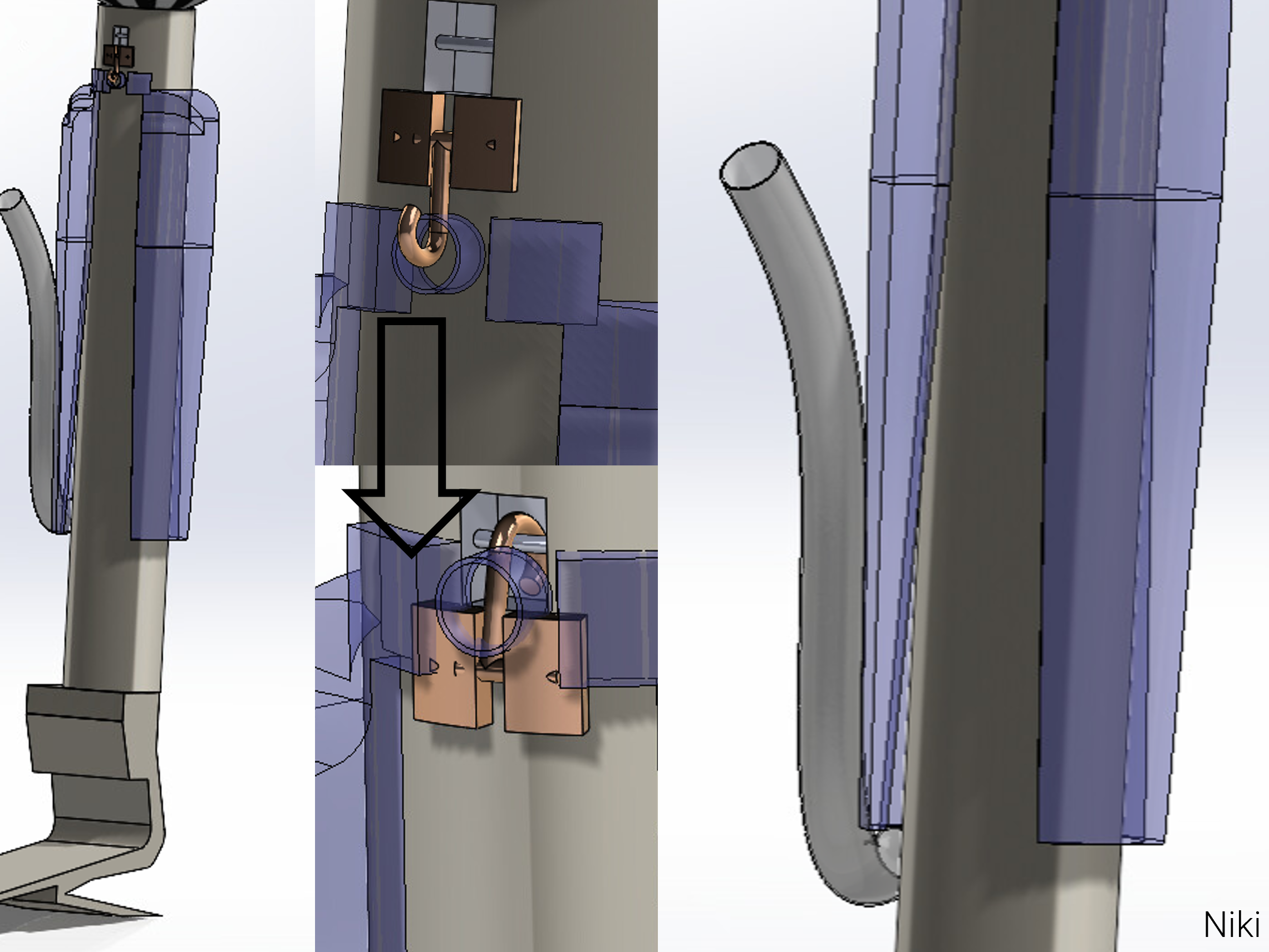
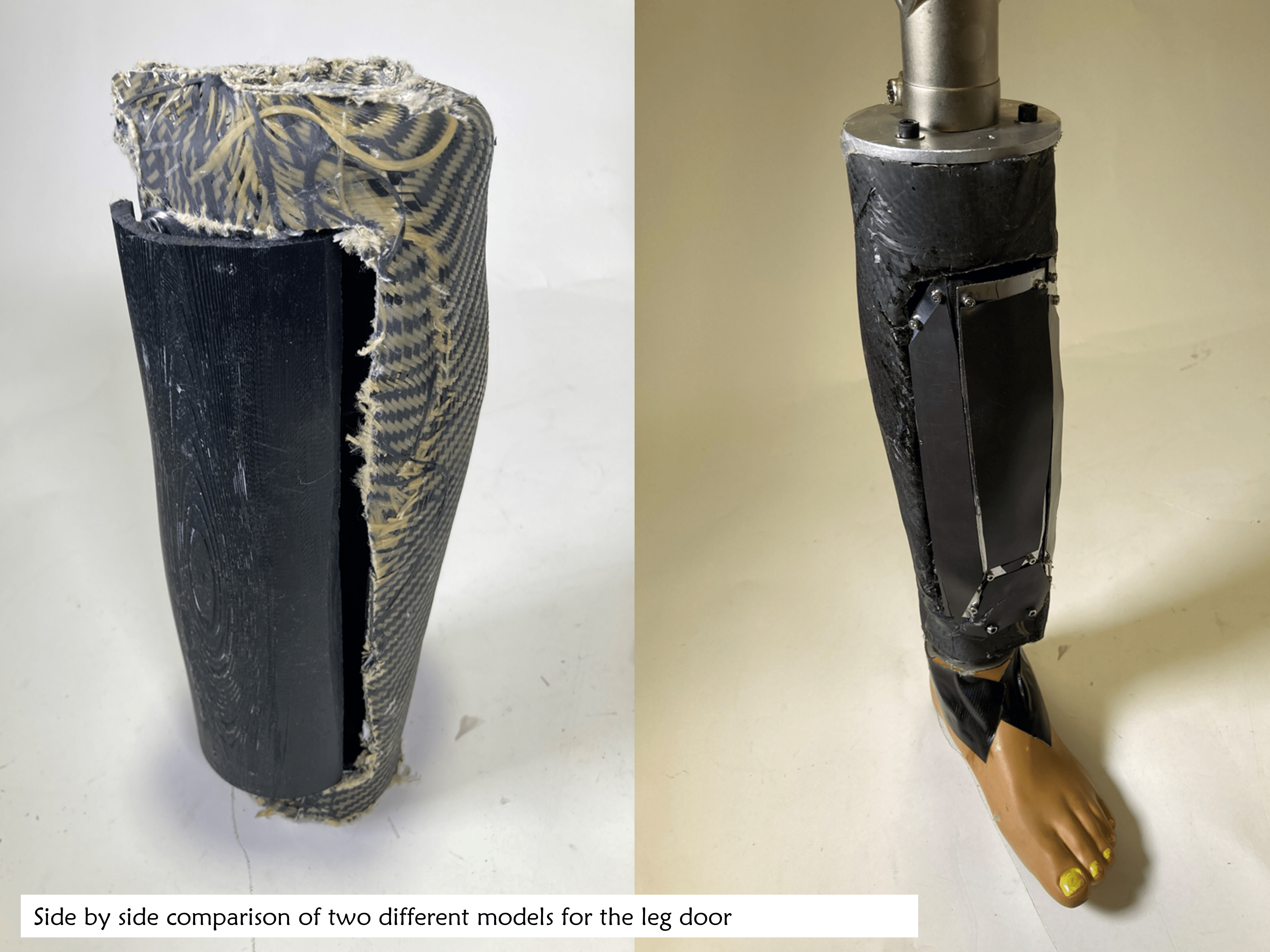
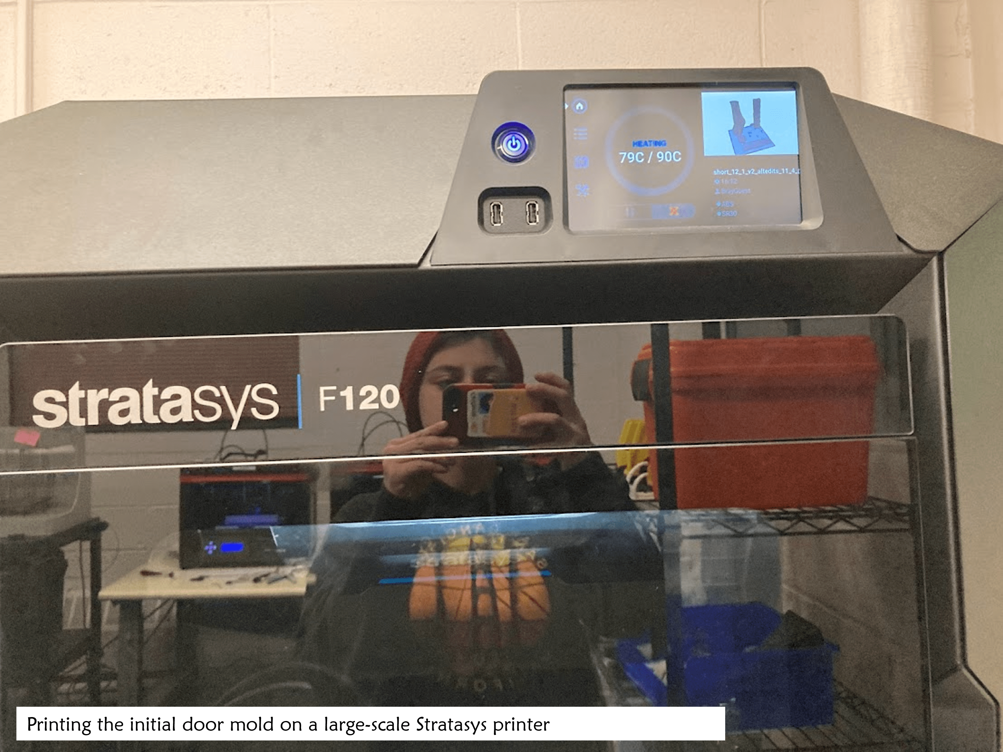
Door Assembly and Integration
While we initially tried to layup our door component, we found that Carbon fiber layups on the door would not secure well to the material and made it difficult for us to align the door with the body of the leg. Given that our door would be supporting minimal weight and that a carbon fiber door would solve more of an aesthetic purpose than a practical one, we opted to instead, shell the door with aluminum. I cut and bent aluminum to form a shell around the door and then secured this into the 3D printed model. A major struggle point for us regarding the door was figuring out how to have a close alignment of the door with the body of the leg since the carbon fiber layup made it difficult for users to have clean edges. Additionally, I struggled to place our hinge components in a way that would both allow a good swing radius for the door and while simultaneously securing the door close enough to the body for a tight and secure fit since I had CADed the door and leg with a relatively low tolerance between the two. In the end, I opted for a friction hinge to allow for easy static movement of the door once the piston had detached from a notch at the top of the door.
Electronics
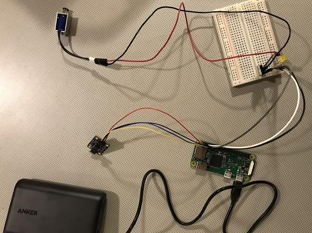
While Niki, David, and I moved forward with fabrication, Megan took the lead on electronics. Her system integrated a mini push-pull solenoid, a Time to Flight VL6180X distance sensor, and a Raspberry Pi 0 to extrude and retract the solenoid relative to the measurements of the distance sensor. She also integrated this into a website to allow for manual control of the Solenoid during testing. A github for the electronics can be found here.
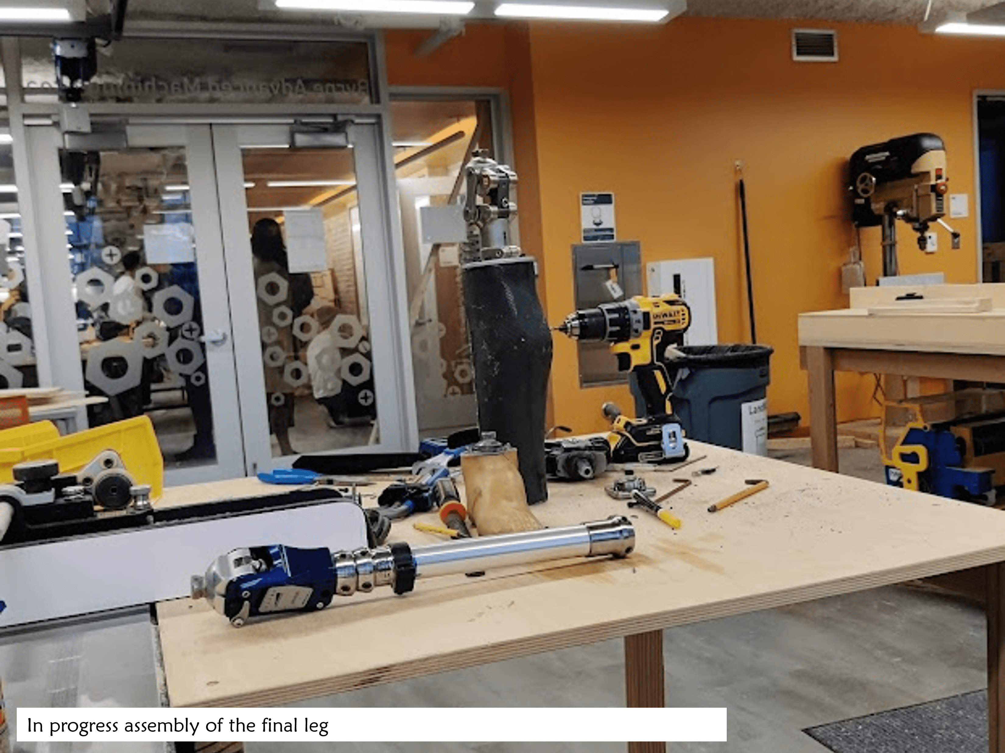
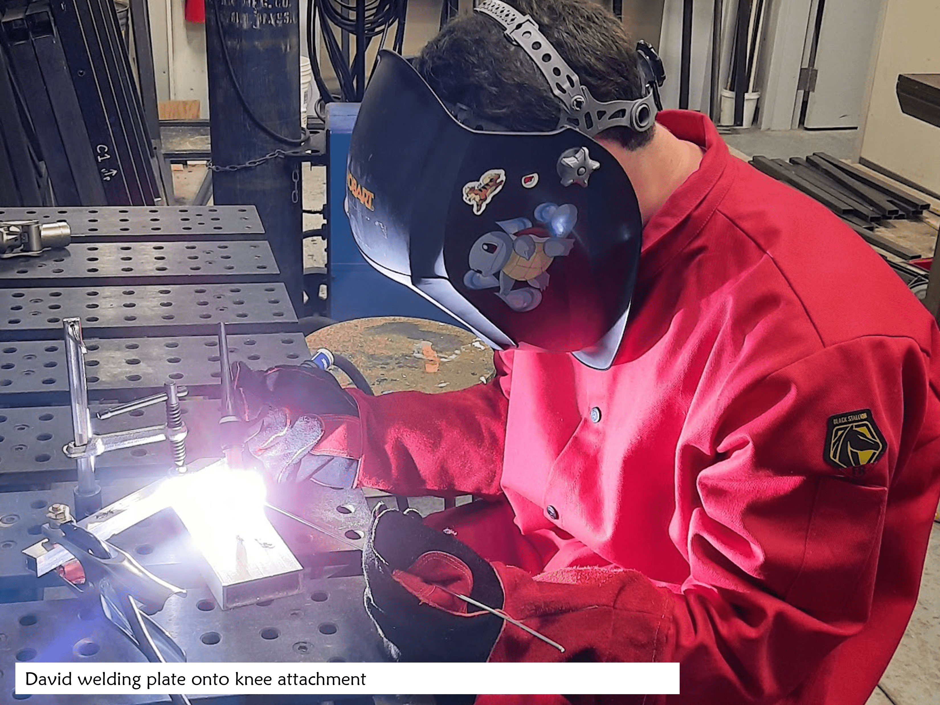
Final Assembly and Integration
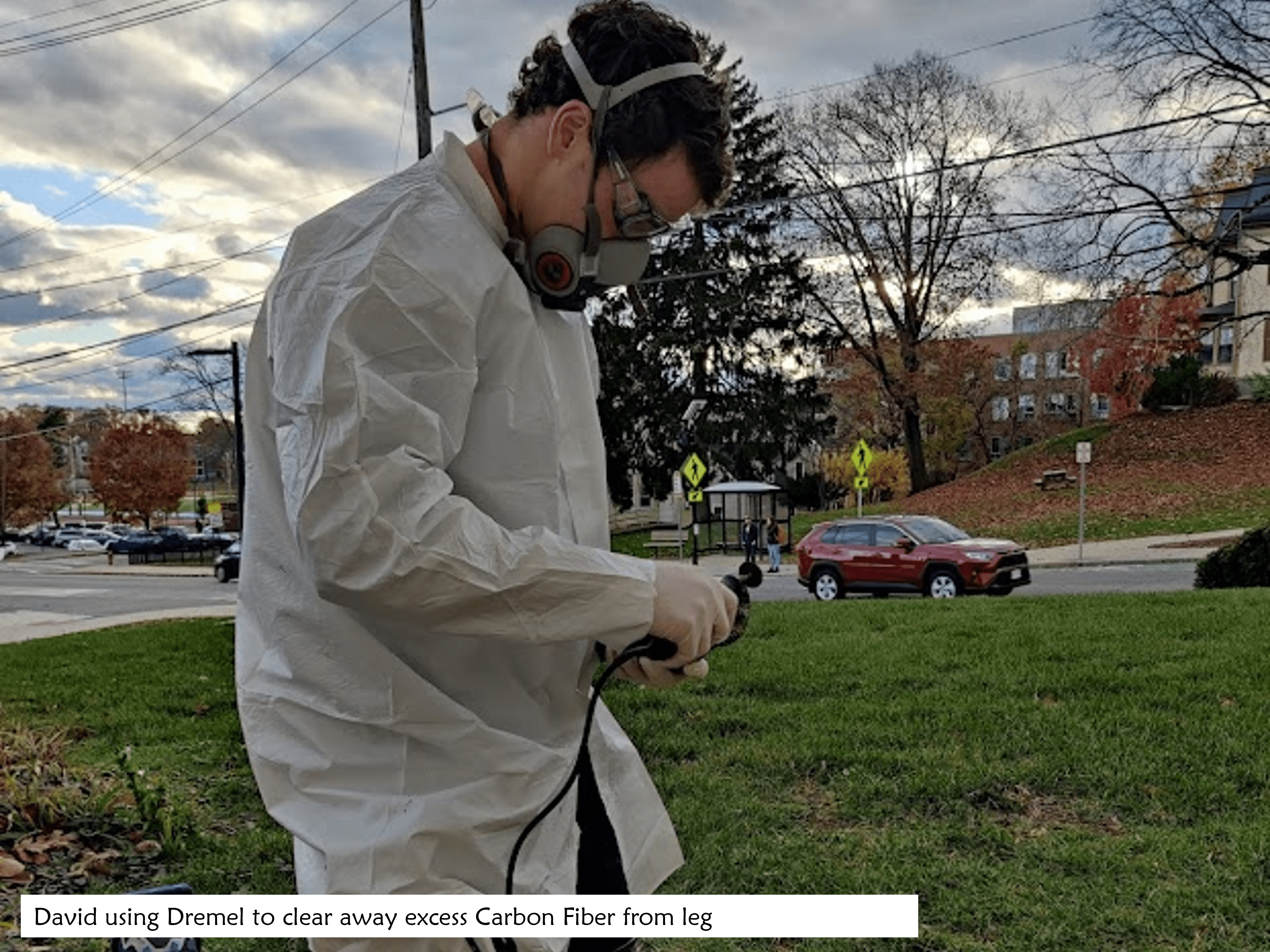
In the "tale as old as time" of manufacturing, one of the most difficult parts of our build process was getting our system to fit together. Our team had several modular parts that needed to fit into one leg: our Carbon Fiber exoskeleton, the Össur mechanical knee, the electronics, our door, and the locking mechanism. To integrate our knee, David welded a plate onto a metal shaft compatible with a universal pyramid adapter. Meanwhile, I worked on the compatibility between the leg and the door. We dremeled and chiseled the leg to allow a better match up with the door and I outlined the door in aluminum to fill in some of the gaps where the two met. For the electronics, I designed a solenoid mounting system that would let the solenoid slide into a holding point in the door. I also designed a static hinge mechanism to attach the door to the main body of the leg.
Final Product
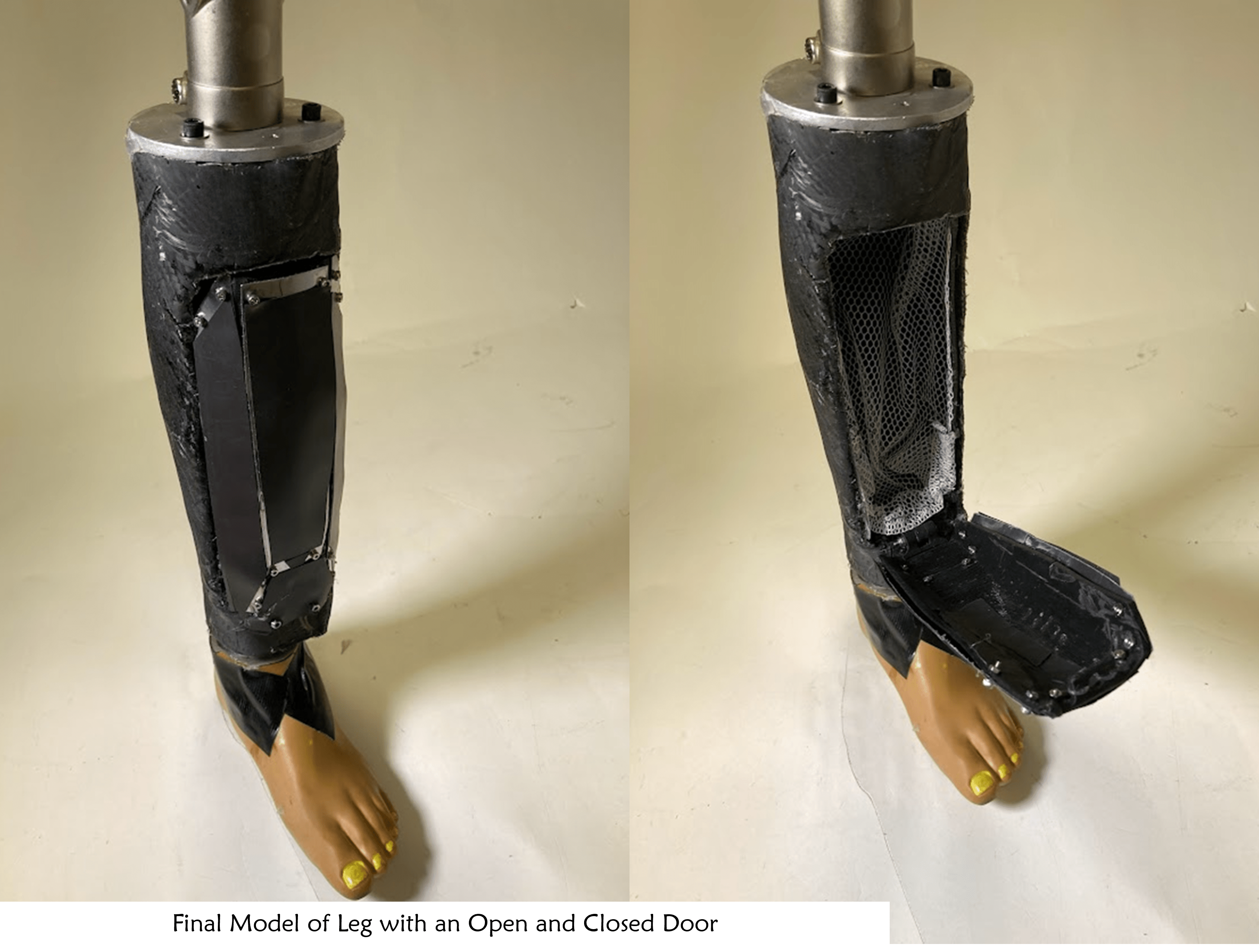
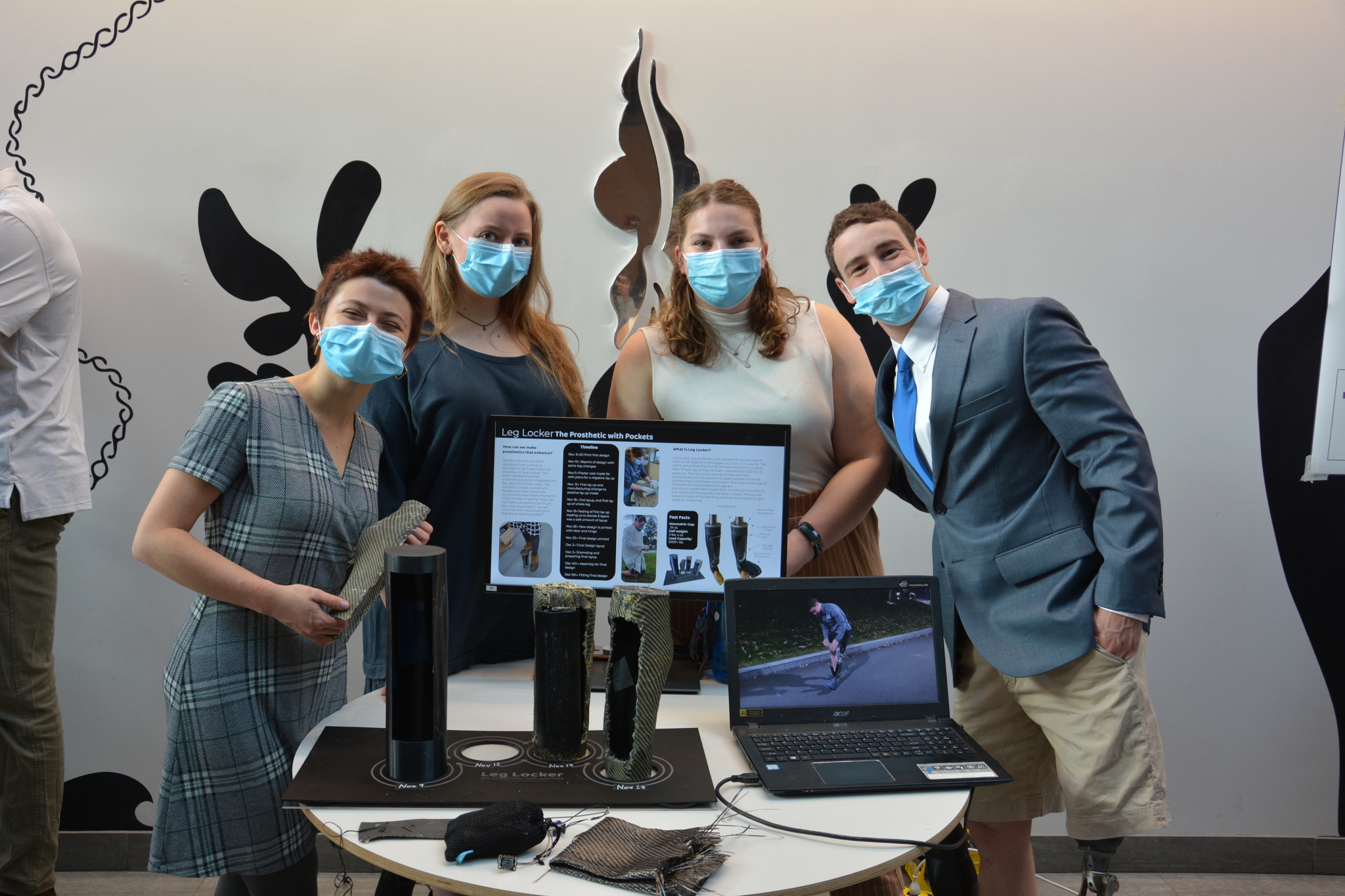
After a semester of work, we presented our final product in a showcase to stakeholders and the Tufts Community. The final version of Leg Locker holds a 2000+ lb capacity along the body of the leg and has a volumetric capacity of 24 oz. The calf and leg are also lighter than the average leg to allow for extra weight to be used for storage. Our final prototype is composed of 6 layers of carbon fiber layup around a PLA 3D printed exoskeleton for the body of the leg. The leg connects to standard knee and foot components with a metal plate welded to a shaft. . The internal storage of the knee can be accessed through an aluminum-reinforced hinged door and the interior of the leg is softened with a net to prevent stored items from moving around. A solenoid mounted to the interior of the leg locks the door in place. This can be turned on and off by bending the knee at an upward right angle for 5 seconds.
Reflection
Going into this design process, I hadn’t had the chance to work on a long-term project from start to finish and it was rewarding to be able to carry something from concept to final product. I think seeing that process of development for a project like the Leg Locker was exciting for me since David worked on our team. Where many other groups in senior design made products for a very removed user and or situations, developing the Leg Locker felt very self-directed and tied to real applications.
Tolerance with people
My team for senior design was an absolute joy to work with, so “tolerance” probably seems like a terse word to use when describing what I’ve learned from them. However, I do mean “tolerance” in the best way possible. While far more than “tolerable” to work with, I think part of the reason we worked well together is because of our willingness to show tolerance and patience with each other. Throughout this design process, everyone on our team had moments where they were sick, tired, stressed, or couldn’t bring their best self on a particular day. Having tolerance and understanding for each other during these times offered a lot more room to fail and I think let us work harder in some ways. Similarly, when there were differences in communication style or expectations within our team, we communicated that and took time to work out those differences. Having tolerance and patience for each other throughout this design process let us help one another and work through issues as a team.
Tolerance with parts
Ah, the difficulties of integration! When building the leg locker, our team focused on making really good individual components: our carbon fiber layup of the leg, the electronics system, and our door component. However, we put less time and energy into the points of integration between these systems and these eventually ended up being the weakest point in our system: the fit between the door and the body, the attachment of the electronics to the leg, the material strength of our hinge, and the weld attaching our aluminum plate to the knee. We put integrating these parts off until the end and spent the least energy making sure they were strong and durable. When we assembled our leg, these parts were the weakest. This was made abundantly clear after our demo when David jumped on the leg and it failed along these points.
Building and Technical Skills
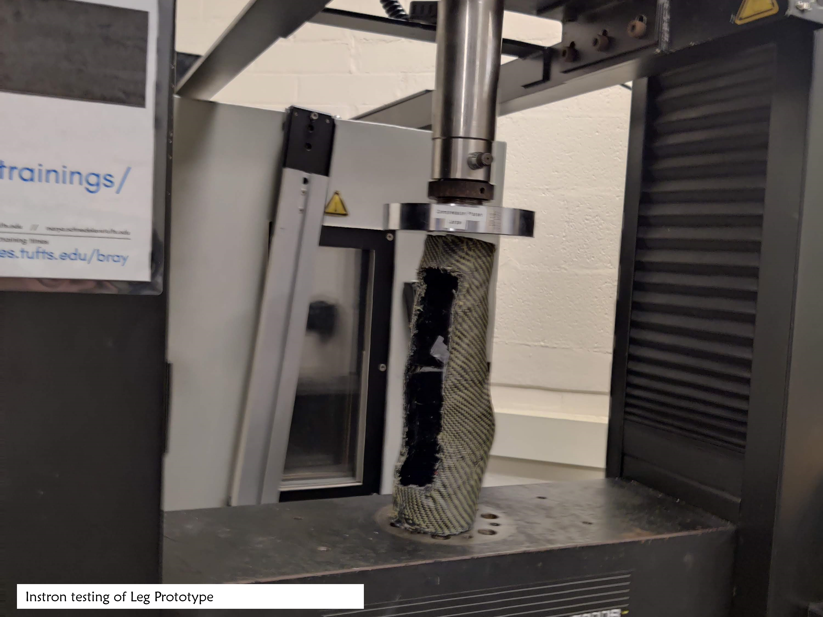
Throughout building Leg Locker, I had the chance to learn new hard skills and build on abilities I have picked up on in the past. Carbon Fiber Polymer Layup and Composite manufacturing are both new areas for me. I felt grateful for the chance to learn about both during this process. It was similarly exciting and rewarding to verify the strength of our layup on the Instron machine (it can hold a 2000lb+ load!). This project also let me practice some of my existing skills including SolidWorks, SolidWorks simulation, 3D printing, and basic fabrication.
Storytelling and Marketing
On the “soft skill” side, I think I learned a lot by figuring out the right way to tell a story about Leg Locker. In some ways, this project followed the specialized design model common in assistive technology and is made with David’s needs and preferences at the center. However, there are also a lot of exciting conceptual elements behind an idea like Leg Locker, and the concept of “prosthetics with enhanced functionality” has a lot of application outside of David’s particular needs. Similarly, since this is a student project, our learning and process are in many ways more important than our end product. Combining these elements into one story and presenting that story to others has been an interesting and educational process.